This review page is supported in part by the sponsors whose ad banners are displayed below |
 |
 |
Here is the 'second harmonic' version showing the input degeneration I just mentioned (R11 and R12) and also a provision for output degeneration (R13 and R14). |
|
It so happens that the second harmonic character we talked about is kind of random due to the imperfect matching of the parts. Typically you will see some measure of second harmonic in the output and that is ordinarily what you would want. When you build it you might find that you didn't get the amount of second harmonic you were looking for. Maybe it's not in the proportion you want or maybe you want to null it out altogether to get the lowest possible distortion figures, leaving only third harmonic. These are all decisions you can make and I always encourage people to try it. You might like some particular result. There are people who like purely third harmonic and presumably there are people who prefer purely second and people who like a slight mixture.
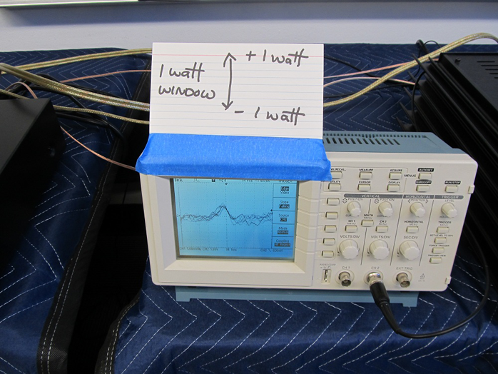
Recall that even if you design for second harmonic, you will tend to get more and more third as the power goes up. In an amplifier with dominant second harmonic rated at 20 watts, you will start seeing lots of third above 10 watts. I have to add that down the hall we have a system with this amplifier. We are running an oscilloscope watching the output with what I call the '1-watt window' where the top and bottom of the screen show instantaneous peaks at 1 watt and the image freezes momentarily on peaks above a small fraction of a watt so you can see the waveform. An amplifier rated at one-half watt rms can just make it to the top or bottom of the screen. With music this 1-watt peak will occur with average music levels of 0.1 watt or less. The remarkable thing is that with efficient speakers—these are 94 dB/watt—1-watt peaks are really pretty loud. Sometimes you want to turn it down. Where I come from, 1 watt is usually enough.
|
 |
If you are interested in adjusting the harmonic structure in this amplifier, there is a nice easy place where you can do it. I have added low-value power resistors (R13 and R14) in series with the Source pins of the output transistors. Typical values for these would be 0.025Ω to 0.1Ω. If you leave R13 at 0Ω and put 0.05Ω for R14, you will find yourself with a positive-phase second harmonic. By this I mean there will be expansion as the wave goes positive and compression as the wave goes negative. If you have a negative-phase second harmonic, you could use this approach to null it out. If you leave R14 at 0Ω but set R13 at a small value, you do the opposite either creating a negative-phase second harmonic or nulling an existing positive-phase second harmonic.
The two phases of the second harmonic do sound different. In fact the most consistent observation people have reported is that positive phase has a little more projection to it, that it's a little more in your face and immediate. Negative phase tends to add more depth. This is something you can play with and moving on to the next slide, for this one we credit Patrick (EUVL) on DIYAudio. What he did was come up with a variable version. Why not put a pot on it? So here you can adjust P3 and P4 up and down, trimming the relative perfection of the symmetry, creating or nulling the second harmonic.
|
|
By the way the numbers I showed you before where there was generous second-harmonic content - those were without either form of trimming. You can trim this to make the numbers drop dramatically. If you are chasing the double-0 distortion numbers, this is a perfectly fine way to do it.
You can look at the popular F5 project and see a version where we did the same thing but on the input stage. It does however take a distortion analyzer to see these things. If you just want to listen to different settings that's okay but if you want it calibrated, a distortion analyzer is the way to go.
|
|
|
As an aside, whenever I use Fets I put a Gate-stopper resistor in the design to prevent parasitic oscillation. Here R7 and R8 at 47.5Ω are used. You can often run these amplifiers without them but they will not be reliable. On this amplifier I originally took the Gate stoppers off because I like to remove all the parts I can and only grudgingly put them back. Without Gate resistors it seemed to work fine but I discovered parasitic oscillation during turn-on. For a few seconds while the output stage was biasing up, the output stage showed oscillation and then behaved itself when full bias was achieved.
While we are talking about adding resistors to pins, when you add resistance at the Source pin you alter the apparent characteristic of the transistor and this is known as degeneration. Degeneration is generally thought of as a form of feedback but I always make a point of distinguishing between degeneration and loop feedback (which by the way we are also doing here – we have a feedback loop). You can degenerate this circuit at the input and output devices to control the bias current or adjust the gain as we have seen above.
As a push-pull Class A amplifier we traditionally expect it to operate in Class A to peaks of twice the value of the bias current. With degeneration a circuit designed to operate at 30Wrms into 8Ω in Class A would by definition leave Class A at 60-watt peaks. Here the actual bias of 1.55 amps would be expected to give 3.1 amps peak output, a 76-watt peak into 8Ω (with adequate supply voltage) and half of that (38 watt peak) into 4Ω. This calculation of the bias and the 'Class A-ness' of the circuit depends on the output devices having significant Source resistance which is generally the case. Fets and tubes have what is known as a 'square-law' characteristic which means that as you raise the input voltage to the Gate, the Drain-to-Source current increases disproportionately. In a single-ended design this produces the familiar second harmonic. Using degeneration resistance tends to remove this effect by adding a linear component to this characteristic. You can't imagine the number of emails and phone calls I get wanting to know exactly at what wattage any given amplifier leaves Class A. Now I have to take the blame for some of this, having written an article called Leaving Class A.
... (audience snickers)... Some people have become overly concerned about where an amplifier leaves Class A as if there's going to be a klunk or some other noise that accompanies it or something. However in a highly-biased square-law circuit, this point is approached asymptotically and there is no big discontinuity to talk about. Often you can't see it on a distortion analyzer waveform.
On the other hand, Class A is Class A and we like as much as we can afford. In a circuit like this we have square-law components that are working in high-bias complementary push-pull.
Jan Didden—here in the audience and publisher of Linear Audio—recently had an article about a square-law amplifier where the major thrust of the design was “I can get you more Class A with less bias current”. In other words you can make a Class A amplifier more efficient by exploiting the square-law characteristics of the devices. I've done some similar things. 40 years ago my first commercial amplifier was based on the premise that everyone wants Class A but nobody wants the heat.
|
 |
If you don't degenerate the output devices—that is if you don't use Source resistors—the square-law characteristic sees to it that you are going to get a wider band of Class A operation for a given bias. I took a measurement of the F6 down the hall (with no degeneration) which was was biased at 1.55 amps. With degenerated devices I would expect a bit more than 38 watts peak into 4Ω. Without degeneration it left Class A at 64 watts.
One thing you have to watch out for when you run devices without degeneration is the thermal coefficient of the transistors. Generally they conduct different amounts of current at different temperatures with the result that they move to a different bias point. Many, particularly bipolar transistors, will simply run away. They conduct more and get hotter and then they conduct more...
The R100s have a "0 temperature coefficient” in the region just above 1 amp which is one of the reasons I can easily run this amplifier without degeneration. If you bias it at an amp and a half at operating temperature, it will not drift enough to worry about. An additional benefit of operating at such a point is that it doesn't suffer the so-called 'thermal distortion' that some designers have talked about. Not all devices out there are so well behaved. There are people building (and selling) amplifiers (most of them bipolar it seems) who swear by the idea of not having emitter resistors (the equivalent of Source resistors on a Fet or Cathode resistors on a tube). They're saying things like “the dynamics are incredible! It's the best sound I ever heard!” for all of ten minutes...(audience laughs)...
|
|
|
If you want to perform harmonic content adjustment without degeneration, there are a couple of options. First you can carefully select the parts for transconductance to favor the desired harmonic content. You can also take some value of resistance and place it across the secondary coils of the transformer so as to load one slightly. They can take as low as a few hundred ohms without too much of a performance hit. For me it's just a matter of picking the slightly higher-transconductance part, putting it on the positive side for positive-phase second harmonic or on the negative side for negative phase. Lastly of course we can note that degeneration values at 0.05Ω or so are not so high that you don't get a good deal of square law action anyway. You can still do this and enjoy
an expanded Class A region though to a lesser extent. So that's our circuit.
It has a power supply and here is the mono version: |
|
You've seen this supply many times and here it is again. It's got 18-volt secondaries that you can get from Antek or Plitron. You can wire it for 240V or 120, it's got a thermistor isolating the analog ground from the hard chassis (earth) ground giving it a safety connection but at the same time it has enough resistance to discourage ground loops. The secondary uses CRC networks to reduce the ripple noise.
|
 |
  |
 |


