 |
|
|
By late January, I was booked to visit Nagra in Romanel-sur-Lausanne to pick up my loaner and take a few assembly photos. Matthieu had organized their production schedule accordingly. Before we see the factory shots, here's a basic circuit diagram to help us know what exactly we're looking at with the Classic Amp. Again, the two-stage PSU starts with a traditional 400VA transformer --> diode rectifier --> filter capacitor type which is followed by a power-factor-corrected switching supply. Multiple polypropylene caps, self-inductance coils and six 47'000µF electrolytics show up for those tasks. The input circuit includes a signal-sensing mechanism to default to standby after 15 minutes of no signal should 'automatic mode' be selected. The gain circuit combines a double current-transfer drive stage and a pair of class A/B common-source push/pull Mosfets. This arrangement is said to be so precise as to require very little negative feedback even for low-impedance bridged mode. The security circuit monitors thermal and output-stage overload conditions to disable the power circuits via relays should protection be required. The same relays are active during the soft-start procedure. The micro-processor control circuit behind the front panel oversees start, stop, standby, automatic and mute modes plus the security circuit and also delivers the clock signal to the PFC circuits.
|
 |
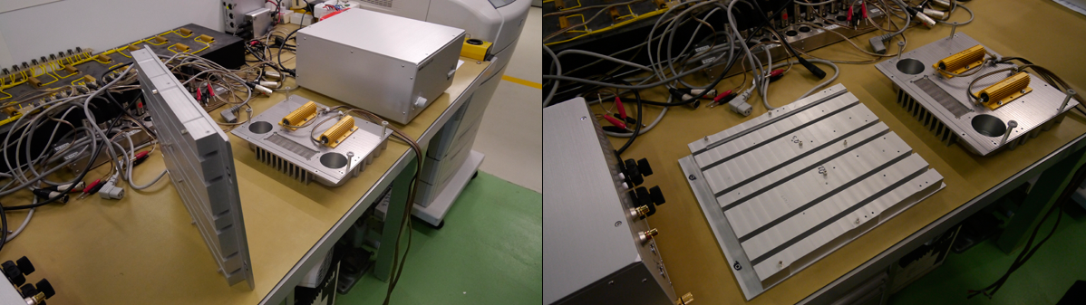
At this amplifier burn-in station with copious load resistors, we see a Classic Amp, before it the underside of an MSA heat sink turned upside down onto its trademark hood ornament; and in the front of it a nude Classic Amp heat sink with its strategic grooves which funnel air to the rear vent. By contrast, this shows off the Classic's increased aluminium mass to accompany its higher power and class A dissipation.
|
 |
Here we see the mother board and PFC modules mounted to the heat sink. The white arrows point at the power Mosfets bolted directly to the aluminium stock beneath the board. To the left, top to bottom, we see the rear panel, the power transformer, the security module and the transformer mounting plate. Leaning against the front of the partially assembled amp is the face plate from its inside.
|
 |
|
|
|
|
At left we see the transformer mounting plate and security module installed; at right the transformer seated without its connections yet wired up.
|
 |
Finally we get to the Exicon Mosfets used in the Classic Amp which are different from the MSA's output transistors.
|
 |
Next comes burn-in central for a batch of HD DAC decks...
|
 |
,,, followed by a pre-production board for the Classic DAC whose power supply integrates on the motherboard.
|
 |
|
 |
|

|

|
